AprilTagを利用した仮想物体の画像表示 (Augmented Reality)
1. はじめに
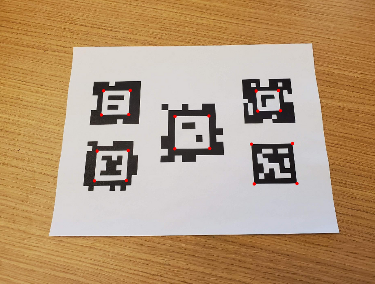
本記事では、以下の画像のように、画像中のARマーカーを検出する方法についてまとめます。
まず、画像処理によってAprilTagを自動検出します。そして、そのAprilTagを底面とする立方体を可視化するために、カメラの位置や向きを自動的に計算します。
 このような処理を動画の各フレームごとに行うことで、AprilTagを検出しながらカメラの位置を予測し、その位置に立方体を可視化することができます。

また、カメラの内部パラメータや外部パラメータの計算方法については、カメラキャリブレーションによって求めることができます。内部パラメータはあらかじめ計算しておき、外部パラメータはAprilTagやそのパーツの位置情報を利用して推定します。
以上のように、画像処理やカメラキャリブレーションによって、AprilTagを検出し、カメラの位置や向きを計算して立方体を可視化することができます。2章以降で、その詳細やコードについて説明します。
また、本内容は以下のスライドにもまとめています。
XRミーティング 2023/08/16 #XRMTG
にて発表した資料になります。
2. AprilTagを含む画像から立方体を可視化するための手順について
2.1. 概要
具体的なプロセスは以下の通りです。2.2以降で補足説明を行います。
1 カメラの内部パラメータをチェッカーボードなどを利用して求めておく:
内部パラメータを計算する方法については以前のブログの記事でも紹介しています。よろしければこちらの記事の6.1をご覧ください。
2 AprilTagを自動的に検出する:
以下の画像のように、画像中からAprilTagを自動的に検出します。ここではTagの種類(family)や大きさを事前情報として与えています。
AprilTagの自動検出のより詳しい説明については以下のページをご覧ください。
3 カメラの位置と向きを推定する(外部パラメータの推定):
2にて求めたAprilTagやそのパーツの位置情報を利用してカメラの位置と向きを推定します。詳しくは、以前のブログの記事でも紹介しています。よろしければこちらの記事をご覧ください。
外部パラメータを計算する方法については以前のブログの記事でも紹介しています。よろしければこちらの記事の6章をご覧ください。
4 ワールド座標系で定義される、画像で表示したい物体の座標を用意する:
上の例では、AprilTagを底面とする立方体を可視化したい場面について話していました。その立方体の頂点の座標は、AprilTagを原点として、(1, 0, 0), (0, 0, 0), (-1, 0, 0) …のように表すことができます。上の例では、この立方体の頂点である、8つの座標の値を準備しました。
5 外部パラメータを利用して、ワールド座標系の対象の物体の座標をカメラ座標系に変換する
3で求めた外部パラメータを利用して、ワールド座標系の立方体の8つの頂点が、カメラ座標系ではどのような値になるかを計算します。これにより、AprilTagを原点としたワールド座標系にある立方体の頂点がカメラの光学中心を原点とした、カメラ座標系に変換されます。別の言い方をすると、それらの頂点は(1, 0, 0), (0, 0, 0), (-1, 0, 0) …のような値ではなく、カメラの光学中心から見たときにどのような位置にあるかに変換します。
5~7の処理を以下に図示します。

6 内部パラメータを利用して、カメラ座標系の対象の物体の座標を画像座標に変換する
5では、カメラの光学中心を原点とした、カメラ座標系に変換しましたが、冒頭のデモ動画のような見せ方をするためには、実際の2Dの動画(の各フレームである画像)のどのピクセルに各頂点が位置するかを計算する必要があります。カメラの焦点距離 (focal length) やスキュー (skew)、画像中心 (image center)などをあらかじめ求めておけば幾何的に解くことができます。
7 画像に表示する
6の計算により、カメラ座標系で表される立方体の頂点が、画像平面上でどのピクセルに位置するのかを知ることができます。この計算を立方体の8つの頂点に対して行い、それらの頂点を結ぶことで、画像上に立方体を描画することができます。
8 1~7のプロセスを繰り返す
以上のプロセスを繰り返すことで、動画全体に対して処理を行うことができます。ただし、各フレームにおいて、AprilTagが検出される必要があります。
2.2. ワールド座標系の点の画像座標への変換について
2.1では、ワールド座標系、カメラ座標系、画像座標(系)にて定められる3つの座標が出てきました。これらについて補足を行います。
ワールド座標系は、対象の物体が存在する座標系のことで、ここではAprilTagを原点とします。カメラ座標系は、カメラの光学中心を原点として、z軸をカメラの光軸と一致させたものです。図中の正規化画像座標は焦点距離を1としたもので、焦点距離fの情報などを利用して画像座標と相互に変換が可能です。
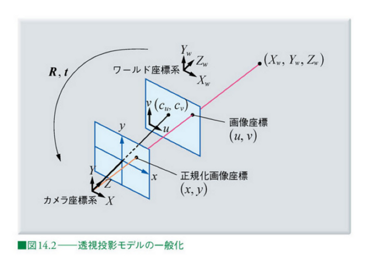
画像出典: ディジタル画像処理 Kindle版 14章
カメラの内部パラメータおよび外部パラメータについては、それぞれ以下の記事が参考になります。
このように、カメラの内部パラメータおよび外部パラメータを利用することで、画像中のARマーカーを検出し、カメラの位置や向きを推定することができます。
2.1の内容と上の記事からそれらの操作を数式で表すと以下のようになることがわかると思います。

...(1)
以下の部分で、ワールド座標系をカメラ座標系に変換し、さらに、

以下の行列と掛け合わせることで、画像座標への変換を行うことができます。

3. ワールド座標系からの画像座標への変換
3章では、2章の流れを実装します。コード全体はgithubにアップロードしているのでそれを参照してください。
まずは、以下に、メインの変換の部分を説明します。以下の点に留意してください。
- あらかじめカメラキャリブレーションをしているため、カメラの内部パラメータは既知である。
- 上の式(1)の、sの値はZcの値と等しくなる。そのため、u, vの値をもとめるためには、計算された値を再度、Zcの値で割ることで求まる
- MATLABコードは以下のとおり
上のプロセスや数式に比べて非常にシンプルに実装することができました。
vertice1 = cuboidVertices(1,:);
camCord = tagPose.R*vertice1'+tagPose.Translation';
intrinsicParameters = [intrinsics.FocalLength(1),intrinsics.Skew,intrinsics.PrincipalPoint(1), 0; ...
    0, intrinsics.FocalLength(2),intrinsics.PrincipalPoint(2), 0; ...
    0, 0, 1, 0];

temp = intrinsicParameters*[camCord;1];
tempNorm = temp/temp(3);
また、立方体の頂点の8点のみでなく、任意の数の点の変換を行えば、画像上に任意の物体を可視化することができます。例えば、ナスの3次元点群に対して同様の処理を行うと、以下のような結果になります。

色々な角度から見たときのナスの様子が可視化されていて楽しいです。 以下に全体の処理についてのコードです。詳細については各コメントアウトを参照してください。
%% Load Video
% Download the video file into a present working directory. Use downloadVideo
% function at the end of this script.

clear;clc;close all
videoFilename = downloadVideo(pwd);
%%
% Load the video to read the first frame.

reader = VideoReader(videoFilename);
I = readFrame(reader);
%%
% Display the first frame.

figure;imshow(I)
%% Load Camera Intrinsics
% Load the camera intrinsics. The intrinsic parameters can be estimated using
% the <docid:vision_ug#btxr8c_-1 Camera Calibrator> app.

data = load("arCameraCalibrationParameters.mat");
intrinsics = data.cameraParams.Intrinsics;
%% Estimate AprilTag Pose
% Specify the size of the AprilTag in millimeters to match the units used during
% camera calibration.

tagSize = 27.7813; % in mm
%%
% Specify the AprilTag family.

tagFamily = "tag36h11";
%%
% Estimate the AprilTag pose.

[~, ~, tagPose] = readAprilTag(I, tagFamily, intrinsics, tagSize);
%%
% The X, Y, and Z axes are represented by red, green, and blue lines, respectively.

annotatedImage = helperInsertXYZAxes(I, tagPose, intrinsics, tagSize);
figure
imshow(annotatedImage)
%%
%
%
% Apply a rotation to the estimated tag pose that rotates the y-axis by 180
% degrees to flip the z-axis.

rotationAngles = [0 180 0];
tform = rigidtform3d(rotationAngles, [0 0 0]);
updatedR = tagPose.R * tform.R;
tagPose = rigidtform3d(updatedR, tagPose.Translation);
%%
% Display the updated world coordinate axes.

annotatedImage = helperInsertXYZAxes(I, tagPose, intrinsics, tagSize);
figure
imshow(annotatedImage)
%% Define Virtual Content
% Define a 3-D cuboid to project onto the top of the AprilTag. The cube is centered
% on the AprilTag and defined to have the same size as the tag.

[cubeWidth, cubeHeight, cubeDepth] = deal(tagSize);

vertices = [ cubeWidth/2 -cubeHeight/2;
             cubeWidth/2  cubeHeight/2;
            -cubeWidth/2  cubeHeight/2;
            -cubeWidth/2 -cubeHeight/2 ];

cuboidVertices = [vertices zeros(4,1);
                  vertices (cubeDepth)*ones(4,1)];

% Activate the code below to display the egg plant instead of the cube
% pt = pcread('nasu.ply');
% loc = pt.Location - mean(pt.Location);
% loc(:,3) = loc(:,3) - min(loc(:,3));
% colMap = squeeze(label2rgb(round(normalize(pt.Location(:,3),1,"range")*100)));
% cuboidVertices = loc*3;
%% Add Virtual Content to Image
% Use <docid:vision_ref#mw_69af89ba-6463-4387-a15c-7c8e1fa5579f |world2img|>
% to project the virtual cuboid vertices into the image coordinate system.

projectedVertices = world2img(cuboidVertices, tagPose, intrinsics);
%%
% Use <docid:vision_ref#btppvxj-1 |insertShape|> to augment the image with the
% virtual content.

figure
augmentedImage = insertShape(I, "projected-cuboid", projectedVertices, ...
    Color="green", LineWidth=6);
% augmentedImage = insertMarker(I, projectedVertices, "circle", "Color",pt.Color);
imshow(augmentedImage)
%%
% Implement world2img function from scratch. Use the first xyz value in the
% vertices.

vertice1 = cuboidVertices(1,:);
% Convert world coordinate into camera coordinate
camCord = tagPose.R*vertice1'+tagPose.Translation';
% Define intrinsic parameters
intrinsicParameters = [intrinsics.FocalLength(1),intrinsics.Skew,intrinsics.PrincipalPoint(1), 0; ...
    0, intrinsics.FocalLength(2),intrinsics.PrincipalPoint(2), 0; ...
    0, 0, 1, 0];
% Convert camera coordinate into xy value in the image coordinate
temp = intrinsicParameters*[camCord;1];
% As the scale factor is not defined, normalize the temp value using
imgCord = temp/temp(3);
disp('Confirm if the value is same as projectedVertices')
imgCord
%% Visualize Camera Pose in 3-D
% Use the estimated AprilTag pose and camera intrinsics to create a 3-D virtual
% representation of the scene corresponding to the image shown above.

figure;
ax = helperShowVirtualCuboid(cuboidVertices);
%%
% Next, use <docid:vision_ref#mw_4d90cc38-ac81-4889-930f-265305142218 |pose2extr|>
% to convert the tag pose to the camera extrinsics, which represent the camera
% orientation and location in world coordinates.

camExtrinsics = pose2extr(tagPose);
%%
% Finally, use <docid:vision_ref#bup3vo1-1 |plotCamera|> to visualize the camera
% in 3-D.

hold on
cam = plotCamera(AbsolutePose=camExtrinsics, Size=15, Parent=ax);
%% Add Virtual Content to Video and Visualize Camera Trajectory
% Repeat the steps above on the remaining video frames.

% Create a video player to display video content.
player = vision.VideoPlayer();

% if two outputs are placed vertically, set it true.
isDispVertically = false;

% Create an animated line to display camera trajectory.
camTrajectory = animatedline(ax, ...
    camExtrinsics.Translation(1),...
    camExtrinsics.Translation(2),...
    camExtrinsics.Translation(3),...
    Color="blue", ...
    LineWidth=2);


videoObj = VideoWriter('renderingDemo', 'Uncompressed AVI');
open(videoObj);

% Loop over remaining video frames.
while hasFrame(reader)

    % Read next video frame.
    I = readFrame(reader);

    % Estimate AprilTag pose.
    [~, ~, tagPose] = readAprilTag(I, tagFamily, intrinsics, tagSize);

    % Update the tag pose to have z-axis pointing out of the tag.
    tagPose = rigidtform3d(tagPose.A*tform.A);

    % Project cuboid vertices from the world to image.
    projectedVertices = world2img(cuboidVertices, tagPose, intrinsics);

    % Insert cuboid into video frame.
    augmentedImage = insertShape(I, "projected-cuboid", projectedVertices, ...
    Color="green", LineWidth=6);
    % augmentedImage = insertMarker(I, projectedVertices, "circle", "Color",pt.Color);
    % Display the augmented video frame.
    player(augmentedImage)

    % Update the camera position in the virtual scene.
    camExtrinsics = pose2extr(tagPose);
    cam.AbsolutePose = camExtrinsics;

    % Update camera trajectory in the virtual scene.
    addpoints(camTrajectory, ...
        camExtrinsics.Translation(1),...
        camExtrinsics.Translation(2),...
        camExtrinsics.Translation(3));
    f = getframe(gcf);

    [h, w, ~] = size(f.cdata);
    if isDispVertically==true
        augmentedImage = imresize(augmentedImage,[nan, w]);
        output = [f.cdata;augmentedImage];
    else
        augmentedImage = imresize(augmentedImage,[h, nan]);
        output = [f.cdata,augmentedImage];
    end
    writeVideo(videoObj,output);

    % Flush the graphics pipeline.
    drawnow limitrate
end
% close the video object
close(videoObj);
% delete the video
delete(videoFilename)
参考ページ
MathWorks: Augmented Reality Using AprilTag Markers
ディジタル画像処理